The HRS infrastructure

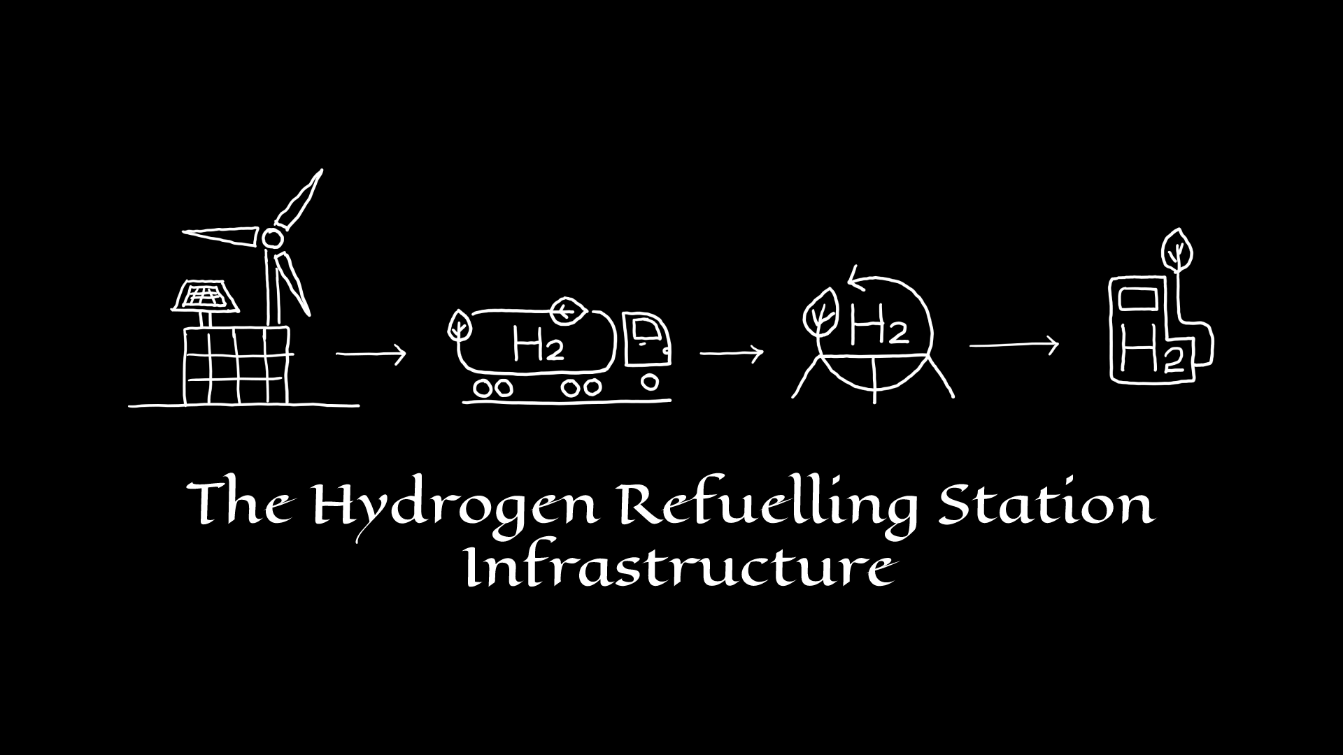
Just like current petroleum refuelling stations that currently keep the transportation sector active, Hydrogen Refuelling Station (HRS) also plays a major role in the emission-free transport of the future. Hydrogen refuelling stations are also an important part of the future hydrogen industry and a successful hydrogen supply chain. The important steps in a typical hydrogen refuelling supply chain are:
1. Power generation from a renewable energy source.
2. Green hydrogen production.
3. Hydrogen transport.
4. Hydrogen storage.
5. Hydrogen refuelling station infrastructure.
Hydrogen refuelling station (HRS) infrastructure
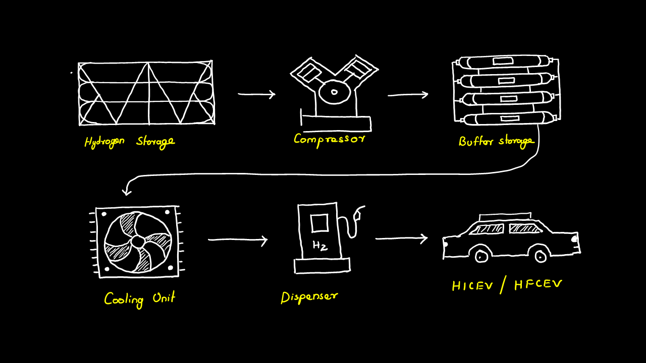
A hydrogen refuelling station infrastructure consists of the following components
1. Compressor.
2. Cryo pump.
3. Hydrogen buffer storage.
4. Cooling unit.
5. Dispenser.
Compressor
Compressors can be regarded as the heart of a hydrogen refuelling station. Since hydrogen must be compressed to the standardized pressure, for refuelling light and heavy duty. There are generally two basic principles of gas compression: Displacement compression and dynamic compression or turbo compression. Due to the small molecular size and high diffusivity of hydrogen Turbo compression is not preferred as it will lead to greater losses. Piston compressors are the most used in hydrogen refuelling stations. The other possibilities technologies include diaphragm compressors and electrochemical compressors. Storing hydrogen in metal hydrides reduces the power used for compressing hydrogen because these storage systems are capable of releasing hydrogen at high pressure.
Cryo pump
Cryo pumps are used when hydrogen is primarily stored in the form of liquid. Cryo pumps are capable of delivering hydrogen either in the liquid form or in the gaseous form. When hydrogen needs to be dispensed as gas the cryo pump works in a combined system involving a pump and a compressor. The liquid hydrogen is fed into the pump using vacuum-insulated tubes which then get expanded in the expander to the required pressure thereby enabling direct hydrogen refuelling.
Hydrogen buffer storage.
Hydrogen in a refuelling station may primarily store hydrogen in the physical or chemical form, but in order to scale up the hydrogen from the production or storage conditions to the refuelling standards (350 bar or 700 bar), buffer storage must be used. Here the compressed hydrogen from the compressor is stored at even higher pressures and is ready for refuelling. The buffer storage of a 350 bar HRS stores hydrogen at 500 bar whereas that of a 700 bar HRS stores hydrogen at 900 bar. This is because hydrogen being a gas flows naturally from a region of higher pressure to a region of lower pressure. Horizontal or vertical steel cylinders capable of holding up to 250 kg of hydrogen are normally used for this purpose. This storage is also called high-pressure storage.
Cooling circuit
The cooling circuit consists of heat exchangers that serve two purposes:
1. Cooling of compressed gas.
2. Pre-cooling.
Hydrogen must be compressed to increase the pressure and reduce the volume. Compression of hydrogen produces heat and hence this excess heat must be removed. There are compressors that use lubricant as coolant and in this case, dedicated cooling during hydrogen compression is not needed.
Pre-cooling is done to prevent the damage caused during the rapid filling of hydrogen. Hydrogen vehicles use either Type IV tanks made of carbon fibre composite or Type III tanks made of aluminium. Hydrogen when not precooled will lead to an increase in the temperature of gas being filled in the tank and could damage the tanks through thermal degradation. According to the filling protocol of the hydrogen refuelling station, SAE J2601 the hydrogen in the onboard storage tank should not exceed 85 °C. The increase in temperature will also reduce the storage capacity of the tank. This increase in temperature is caused mainly due to the following three phenomena:
- High kinetic energy – The high kinetic energy of the fast-flowing gas produces a lot of heat during the filling process.
- Joule-Thomson effect – Hydrogen has a negative Joule-Thomson effect which means it releases heat upon expansion. The expansion of hydrogen through the throttle valve causes the temperature to rise.
- Hydrogen compression – Hydrogen compression inside the tank also increases the temperature inside the tank.
Dispenser
A hydrogen dispenser is responsible for delivering the hydrogen stored in the buffer storage to the vehicle's onboard storage tank. A hydrogen dispenser unit consists of:
- Breakaway coupling: The breakaway coupling prevents the leakage of hydrogen when the vehicle is accidentally driven off.
- Refuelling hose and filling nozzle: The filling nozzle and hose are connected to each other. The filling nozzle is the one that connects to the vehicle tank and is made according to the SAE J2601 standards for the specific filling pressure of the onboard hydrogen tank. Hence these nozzles connect only to the vehicles that can be filled with rated dispensing pressure. These nozzles are also double-sealed and cannot be opened unless connected to the vehicle.
- Vehicle identification and control system: If the dispenser could refuel multiple vehicles, it is also equipped with a vehicle identification system because of different refuelling protocols. The dispenser also has a control system that prevents refuelling at pressures exceeding the maximum working pressure of the vehicle fuel tank.
- RDI: The Refill Data Interface (RDI) is used to establish communication between the vehicle and the dispenser control unit. The RDI collects the data transmitted from the vehicle’s infrared transmitter and sends it to the control unit thereby regulating the refuelling process according to the refuelling protocol. These data include the receptacle type, tank volume, pressure, and temperature. These devices are designed for SAE J2601’s communication refuelling protocol according to the SAE J2799. The RDI is located on the front of the fuelling nozzle and is housed inside an aluminium cylinder with a rubber coating for shock protection.
- Quantity measurement meter: The hydrogen quantity measurement meter measures the mass flow of hydrogen into the vehicle tank and is designed based on the Coriolis architecture.
References:
- Overview Hydrogen Refuelling For Heavy Duty Vehicles. (n.d.). H2 MOBILITY Deutschland GmbH.
- Wasserstoff-Tankstellen. (2022). Linde Gas GmbH Österreich. https://www.lindegas.at/de/anwendungen/wasserstoff_technologie/wasserstoff_tankstellen/index.html
- Think Hydrogen. Think Linde. (2022). Linde Engineering. https://www.linde-engineering.com/en/hydrogen/index.html
- Hydrogen Stations | Fuel stations for hydrogen mobility. (2022). Haskel. https://www.haskel.com/en-de/products/hydrogen-refuelling/hydrogen-station
- Hydrogen fueling equipment. (2022). Nel Hydrogen. https://nelhydrogen.com/hydrogen-fueling-equipment/
- Wasserstoffanlagen | Air Liquide. (2022). Air Liquide. https://de.airliquide.com/unser-equipment/wasserstoffanlagen
- Federal Ministry for Economics Affairs and Climate Action. (2022). The National Hydrogen Strategy. https://www.bmwk.de/Redaktion/EN/Publikationen/Energie/the-national-hydrogen-strategy.html
- Design Considerations | Hydrogen Tools. (0). Indoor Refueling of Hydrogen-Powered Industrial Trucks. https://h2tools.org/bestpractices/design-considerations
- Li, S., Guo, J., Lv, X., Deng, T., Cao, B., & Wang, J. (2021). Research on High-Pressure Hydrogen Pre-Cooling Based on CFD Technology in Fast Filling Process. Processes, 9(12), 2208. https://doi.org/10.3390/pr9122208
- N.B. (2017). GKN’s Solid-state Hydrogen Storage System. GKN Powder Metallurgy. https://www.gknpm.com/globalassets/downloads/powder-metallurgy/2018/gkn-metal-hydride-based-hydrogen-storage.pdf/
- Friedrich, B. (2022). Hydrogenious LOHC Technologies - Wasserstoffhandhabung leicht gemacht. Hydrogenious LOHC Technologies. https://www.hydrogenious.net/index.php/de/hydrogen-2-3/
- Linde H2 refuelling technologies. (2021). Linde GmbH, Linde Engineering. https://www.linde-engineering.com/en/images/Tomorrows-fuel-today-Linde-H2-refueling-technologies_tcm19-632211.pdf