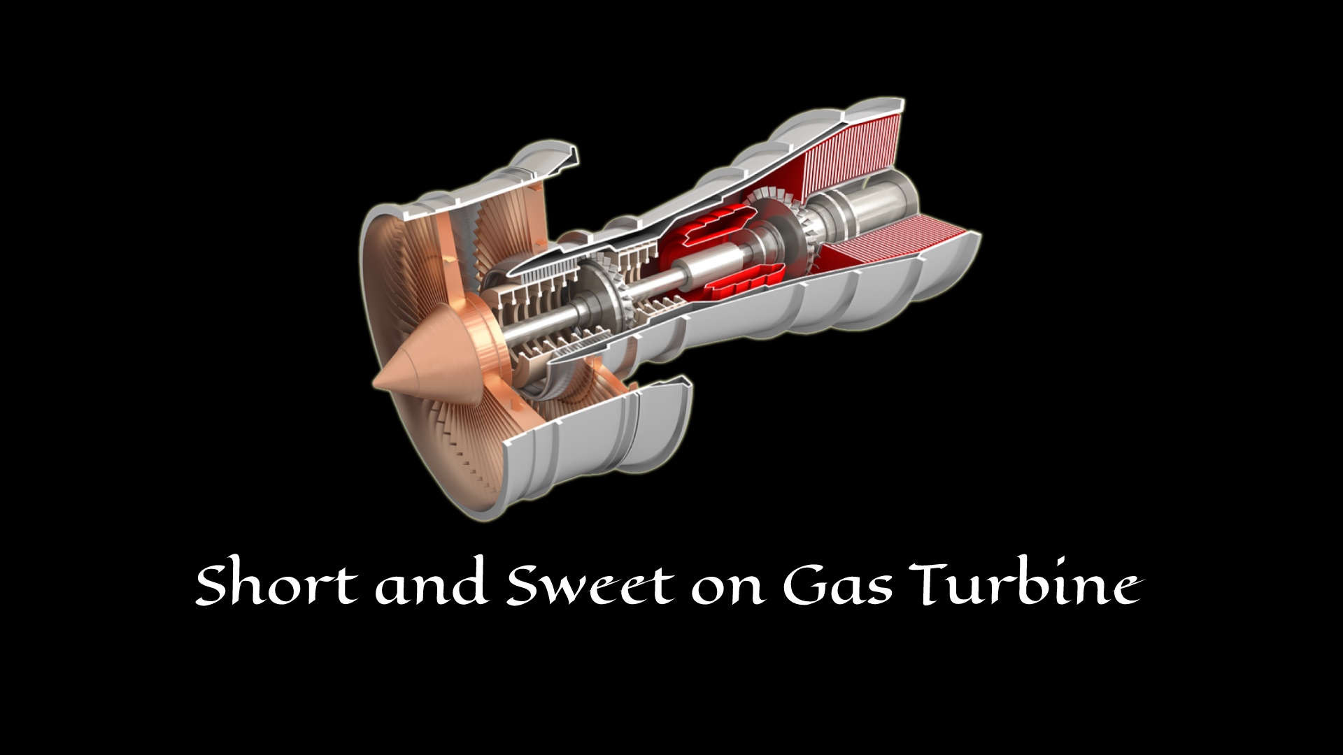
Gas Turbile - Fundamentals

Gas turbines have been in operation for decades now, and their evolution over the years has made it possible for the electrical efficiencies of the combined cycle power plant to reach around 60%. Today, gas turbines are more advanced than in the past and are more flexible, and offer many features, including a higher number of starts, lower maintenance, lower emission, short starting time, and fuel flexibility.
Gas turbines for power generation are giant machines that combust a gaseous fuel in the air to spin the turbine blades that drive a generator to produce electricity. Gas turbines normally run on natural gas, but their emission releases carbon and harmful greenhouse gases into the environment. So today, several pieces of research are being conducted that enable them to combust more than one fuel, namely hydrogen and ammonia. This would eliminate all the harmful emissions from conventional gas turbines.
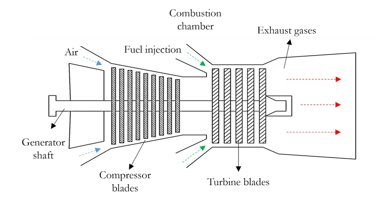
Gas turbines work on the Brayton cycle principle in which fuel is combusted inside a combustion chamber at constant pressure to generate a stream of gases that drives the turbine blades. This is similar to a steam turbine being driven by high-pressure steam. There are two types of gas turbines, internal and external, comprising the same components. A simple cross-sectional view of an industrial gas turbine with its components is shown below and the components are explained in detail below.
Inlet section
The air is drawn in through the inlet section and gets compressed through the compressor blades, raising the compressed air's temperature. This air is then fed into the combustion chamber at higher speeds. This air must also be clean of dust, salt, pollutants, and foreign objects to prevent damage to the engine parts
Compressor
The compressor is responsible for supplying the air inside the combustion chamber at high pressure and is made up of rotating blades on discs and stationary vanes through which the air passes. It has guide vanes at the entry and exit for the air to flow smoothly. This also reduces the losses that occur inside the compressor due to friction and turbulence. The air enters the compressor through the entry guide vanes and leaves through the exit guide vanes. The exit guide vanes are also responsible for the straight-line flow of air into the diffuser upon exit. The compressor consists of several stages through the air flows, with each stage comprising one rotating stage and one stationary stage. The major types of compressors used include:
1. Centrifugal compressor.
2. Axial-flow compressor.
3. Axial-centrifugal-flow compressor.
Diffuser
The diffuser is a divergent duct that connects the compressor exit and combustion chamber entry. It converts the velocity of the airflow into static pressure, and as a result, the air discharged from the diffuser has the highest static pressure and lowest velocity.
Combustion chamber
The air from the compressor enters the combustion chamber through the diffuser, where it gets continuously combusted with the fuel supplied from the fuel injectors. The fuel injector mixes the fuel with the air forming a stoichiometric mixture which is then ignited with an electric spark. But in practice, combustion of a stoichiometric mixture of fuel and air results in high temperature. Hence an A/F ratio in the range of 100:1 is used in order to reduce the inlet temperatures. In a combined cycle-operated gas turbine, the combustion chambers are designed to produce maximum heat with minimum pressure loss. The average flame temperature inside the chamber is above 1900 °C, which would melt the engine's metals. Hence to prevent flame contact with the metal parts, combustion liners and fuel nozzles are used to control the fire. Several technologies are being developed to ensure that the combustion chamber doesn’t produce any harmful greenhouse gases and reduce NOX emissions due to high temperatures. The different types of combustion chambers used in gas turbines are:
1. Can type.
2. Cannular type.
3. Annular type.
4. Silo type.
Turbine
The turbine converts the kinetic energy of the gases from the combustion chamber into mechanical energy. In industrial gas turbines used for power generation, this mechanical energy is used to drive the compressor and a generator to produce power. The high pressure, high[1]temperature gases from the combustion chamber get expanded in the turbine to low pressure and temperature. Just like different types of compressors, turbines are mainly of two types:
1. Radial flow turbine.
2. Axial flow turbine.
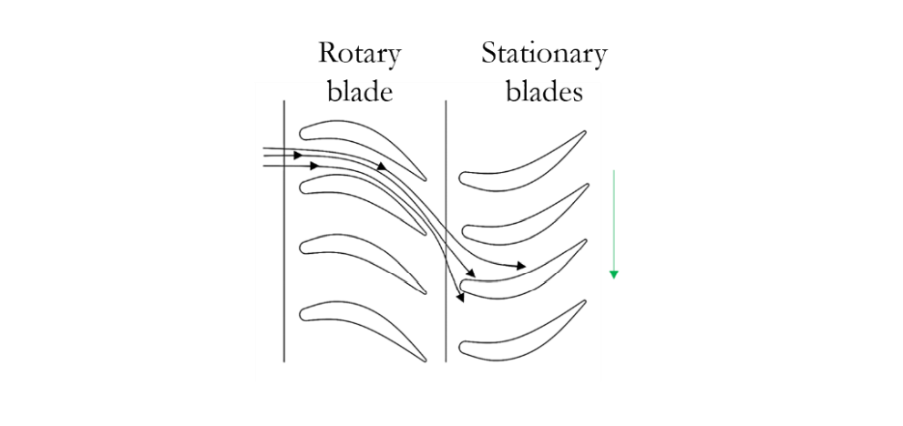
The radial flow turbine works the opposite of a centrifugal flow compressor, whereas the axial flow turbine is similar to the axial flow compressor and consists of several stages of airfoil section blade with each stage comprising a set of stationary and rotatory blades, as shown in the figure below. The rotatory blades are responsible for driving the shaft that runs the compressor and generator, whereas the stationary blades allow for the smooth flow of gases, thereby increasing the velocity of the flowing gases. The base of these guide vanes is sealed so that all the gases flow through the turbine for maximum efficiency.
Exhaust
The hot gases expanded through the turbine blades, exit the engine through the exhaust. Though the energy of the exhaust gases is used up in the turbine, it still has some energy within it that could be used for many applications. Based on the application for which the engine operates, this exhaust duct could be convergent or divergent. The convergent duct further accelerates the exhaust gases producing thrust. This is the principle in jet engines. In industrial applications, mainly in a combined cycle, this duct is divergent so that the heat from the exhaust gases can be used by HRSG, thereby increasing the overall efficiency.
Apart from the above-mentioned components, several other supporting components are necessary for the smooth functioning of the gas turbine. These include:
1. The cooling system – that cools the hot sections of the engine like the turbine airfoils.
2. Bearing and lubrication system – bearings perform several operations like giving support to the rotor and absorbing the thrust developed at the end of the rotor. To ensure the smooth functioning of these bearings, they are lubricated, and hence they are also a primary focus while designing the engine.
3. Fuel delivery system.
4. Compressor wash system.
5. Engine conditioning system.